A Schematic on the Fly”® of Equipment D showing 7 levels of Equipment.
The screen is divided into 3 sections:
Inputs to Equipment D on the left side
Eg. Equipment B and H are inputs to Equipment D so they are drawn on the left side
Equipment D in the middle
Outputs from Equipment D on the right side
Eg. Equipment E and K are on the output of Equipment D so they are drawn on the right side
“Schematic on the Fly”® then repeats this process as necessary.
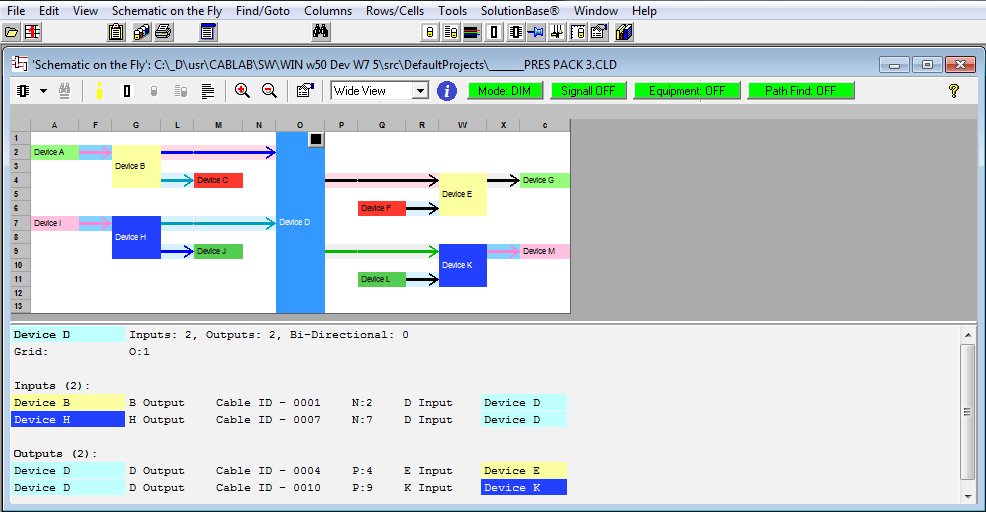
| There are a few other things of interest to note: There are two Tool Bars at the top of the screen: the normal system one and the special local Tool Bar. On the Right hand side of the local Tool Bar are the current settings for Fault Find Assistant. At the bottom of the screen are the details for the currently selected item, in this case Device D. |
| All this without any drawing by the user. |
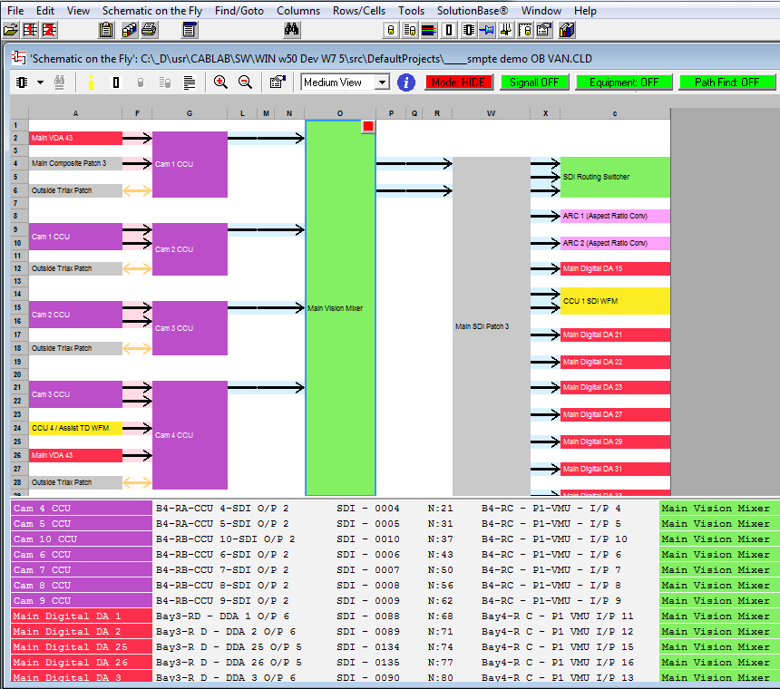
A real world example of “Schematic on the Fly”® including cable data and signal flow
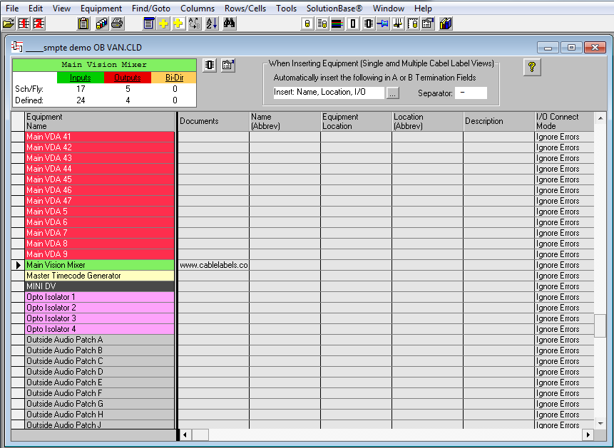
“Schematic on the Fly’s”® Equipment Editor
The Equipment Editor creates equipment and sets its display colors for “Schematic on the Fly”®.
Many more Fields have been added to enable auditing and asset management activities.
Every time an item of Equipment is highlighted, the “real time” connection summary located at the top of the window is updated from the Database.
Often this reduces time by highlighting simple errors, Eg. 2 inputs to the same equipment.
“Schematic on the Fly’s”® Equipment Finder
One of Schematic on the Fly’s”® advantages is its ability to quickly locate any item of Equipment and instantly draw its “Schematic on the Fly”®.
This Finder lists all the Equipment in the Database, the text (Grid W:50) indicates the item is in the currently displayed “Schematic on the Fly”®.
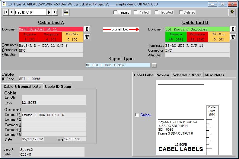
The Single Cabel Label View
This Editor shows a single a cable from the Cable Labels – Cabel Labels Database.
Each end of the cable has fields for: Equipment, Termination, Connector and Attributes. At the end of each field is a button which provides short cuts and “local options”. Short cuts to Schematic on the Fly and the Equipment Editor are also provided. The current status for each end’s Equipment is also shown.
The Cable Labels – Cabel Labels Database system uses a system of “Layouts” that determine which of the fields are printed on a Cabel Label and where. On the right side of the Editor is a preview of how the Cabel Label will be printed.
“Signal Type” and “Signal Flow” defines the type and direction signals flow in the cable.
Cable Identification and physical parameters such as Length and Type.
A number of general fields for any purpose.
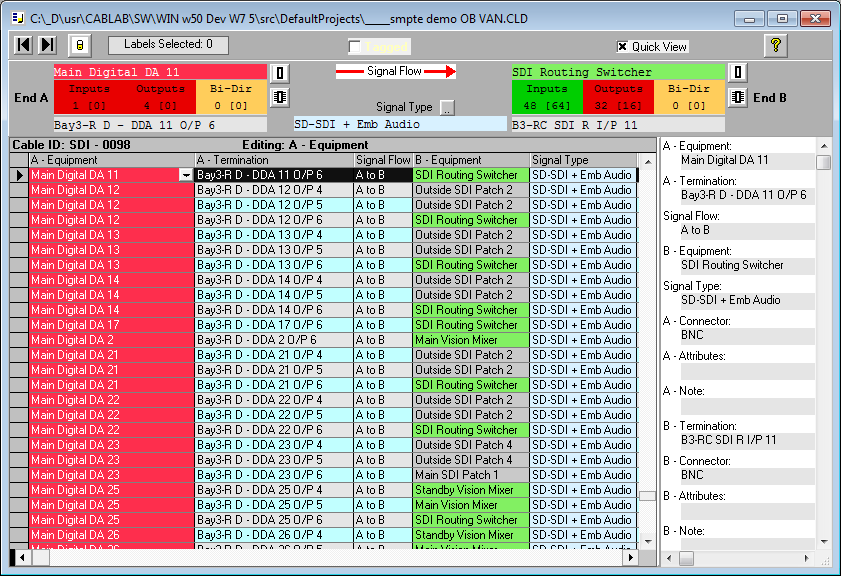
The Multiple Cabel Labels View
This Editor shows multiple cables from the Cable Labels – Cabel Labels Database.
Columns may be ordered, sized or hidden to suit the user and the application. The pop up viewer (right hand side) makes viewing all the fields possible without scrolling.
Short cuts to Schematic on the Fly and the Equipment Editor are also provided. The current status for each end’s Equipment is also shown.
This view is particularly useful when examining a group of cables attached to an item of equipment.
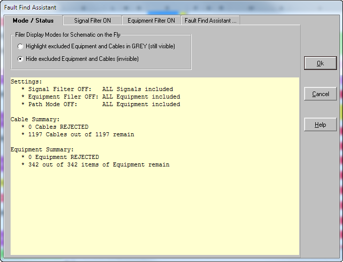
Fault Find Assistant
This is used to tailor Schematic on the Fly’s contents using a number of constraints. It is possible to use one, two or all of its facilities combined, making very flexible and powerful.
Below is the Mode and Status View. The Display Mode either hides cables or equipment (do not appear in Schematic on the Fly) or are dimmed. The lower section is a summary of the current Fault Find Assistant’s operation.
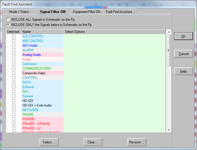
By selecting/de-selecting Signals, Virtual Signals or both, its possible to tailor the resulting SOF display to show only the parts that are relevant.
Below is the Signal Filter View used to perform this task.
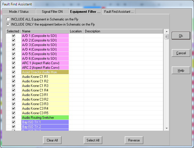
By selecting/de-selecting Equipment it is possible to tailor the resulting SOF display to show only the parts that are relevant.
Below is the Equipment Filter View used to perform this task.
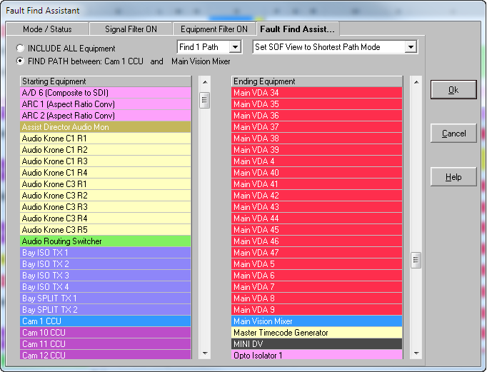
Sometimes it is necessary to quickly find the path a signal travels from one piece of equipment to another.
The view allows the user to select the source (FROM) and destination (TO) items of equipment.
Once this is complete it analyses the cables and equipment remaining (after Signal and Equipment Filtering if they are enabled) to produce a Schematic on the Fly with only the viable paths shown (or un viable dimmed if that option is selected).
Having created a Schematic on the Fly, it then creates a path list between the FROM and TO items of equipment.
The multiple path option (only single path option shown below “FIND 1 Path”) enables the first 20 paths to be found.
These are then made available to Schematic on the Fly as a “click and follow” way to traverse the path.
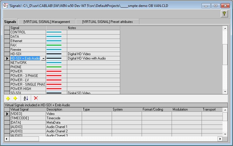
Signal Editor
Cables now carry far more than one signal, often they carry hundreds or even thousands. So its time cable management was brought up to date!
We achive this by replacing the conventional “CAD drawing layers” approach with something far more flexible and powerful that we call “Virtual Signals”.
Our software allows you define your own Signals and “Virtual Signals”, below a screen shot of how it is done….
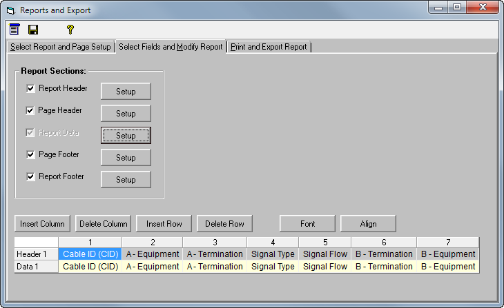
Reports and Export
Our previous Reports and Export have been replaced by a new and more flexible Report Creation and Export Tool.
The image below shows the “Detail” area of a Report under construction.
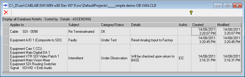
NoteIts
How often does the same “note” or comment apply to more than one item?
Very often, so we have a new facility called “NoteIts”.
Below is a screen shot, notice how a whole path has the same note!
NoteIts have a navigation facility which makes it easy to move between the respective items.
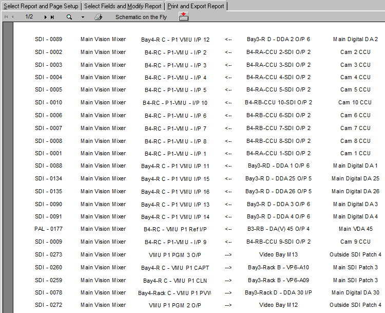
“Schematic on the Fly”® Lists
This is a Construction List created by “Schematic on the Fly”®.
These “equipment centric” lists are ideal for construction and commissioning as they provide all the connections to a piece of equipment grouped together. This style of grouping makes it possible to move efficiently between items of equipment verifying all its connections. They may also be used as an emergency fault finding reference.
Their contents and format are defined by the user and may be exported.
Wiring / Multi core View
The multi column editor enables the internal structure of most cables to be documented.
Each row is a conductor, pair or other appropriate element of the cable.
| A pair or conductor ID. | Description of the pair or conductors use. | Any jumpering or connection details. | The connector and pin assignments. | The cable type, pair or conductor allocation. | The connector and pin assignments. | Any jumpering or connection details. |
SolutionBase® Decibel Calculator
Decibels come in many varieties and sometimes it is hard to remember the calculations and the relationships. This is where SolutionBase’s® Decibel Calculator comes to the rescue.
It has most of the important modes as options but can be set to generic for any others! Illustrated here is dBU (a conversion between decibels and voltage), the user has specified the resistance (top right) enabling power to be calculated.
| Decibel Ratio | Voltage Ratio | Actual Voltage | Actual Power |
Cable Connector Library
Supplied with the Database System is a library of common connectors and cable, this may be expanded by the user as required.